This VFO kit is for the original DSB Digital Transceiver or DSB v. II Digital Transceiver only, but with a user loaded flash to the Atmega328P, can be used as a generic 500KHz-55MHz VFO. See download below.
This product is discontinued
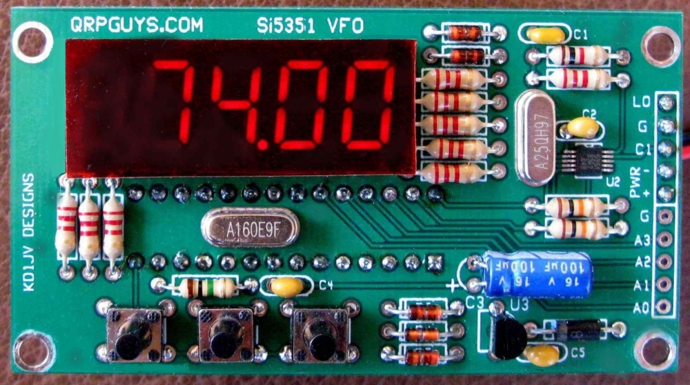
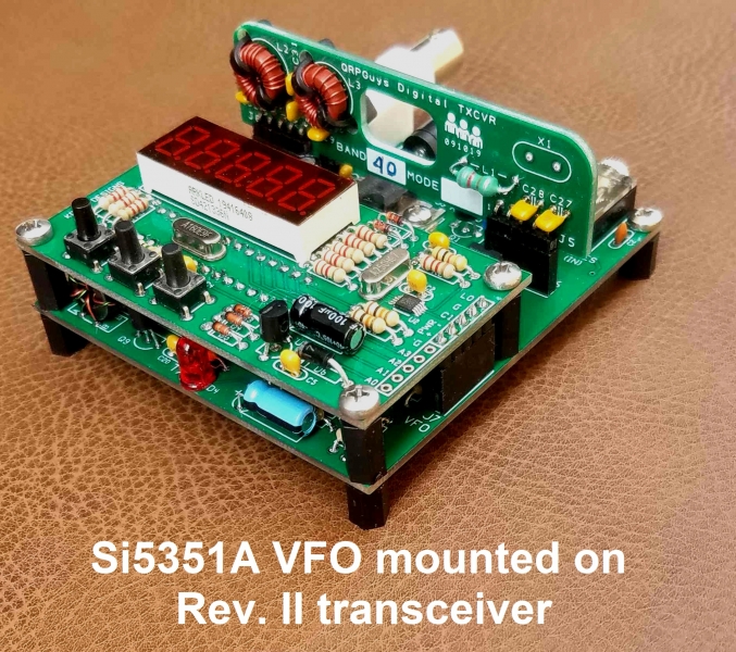
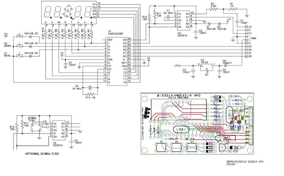
We asked Steve Weber (KD1JV) to design a PLL synthesized VFO kit (160m-10m) for our transceiver kits. His design utilizes the Si5351A/MS53512M PLL clock generator chip, with a single chip Atmega328P µP for control, featuring a five digit LED frequency readout to 10Hz resolution. You simply set the band and frequency with the onboard push buttons. No need to source crystals for additional frequencies or modes. This kit contains all the components and hardware for the VFO to mount onto either digital transceiver pcb, other compatible kits, or if desired, using the four corner holes, mount remotely in your custom chassis. The MSOP10 Si5351A/MS5351M is pre-installed, all other components are through hole. There are additional connections for using a readily available rotary encoder if desired.
The pcb is 3.95″ (74.8mm) x 1.60″ (40.7mm), and mounts directly on either transceiver board, or remotely, using the included hardware. Power required 9-14V @40mA.
As a starting point, the VFO defaults to the FT8 frequency for 160m-17m, and QRP calling frequency for 15m-10m. Specific frequencies for other modes can be easily entered. To use, simply power up and set the digital readout to the specific frequency for your use. The firmware is written with the Arduino IDE and is open source, allowing for the user to modify the sketch to add functions. On a scale of 1 to 5, 5 being the most difficult, this is rated as a 3. The normal tools required are a soldering iron with a small tip, rosin core solder, small side cutters, a small Phillips screwdriver. Allow a couple of hours to build, depending on your experience.
Click here for the VFO assembly manual
Click here for the Digital Transceiver Arduino sketch for customizing
The download below is for using the VFO in a generic setting, not for the Digital Transceiver. We supply the Arduino sketch only and it will be the responsibility of the user to program their own Atmega328P. See the enclosed .pdf for details.
Click here for the generic 500KHz-55MHz VFO Arduino sketch