This product is discontinued.
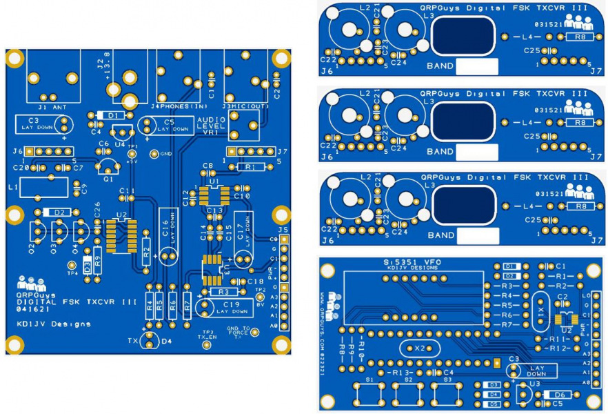
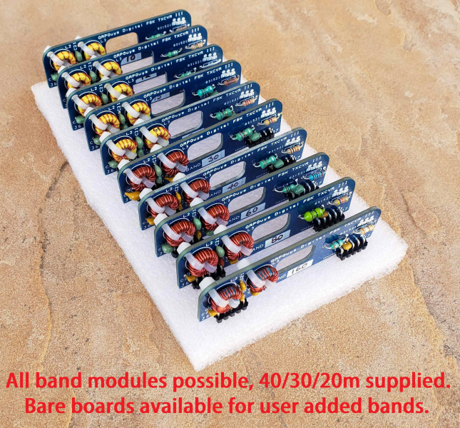
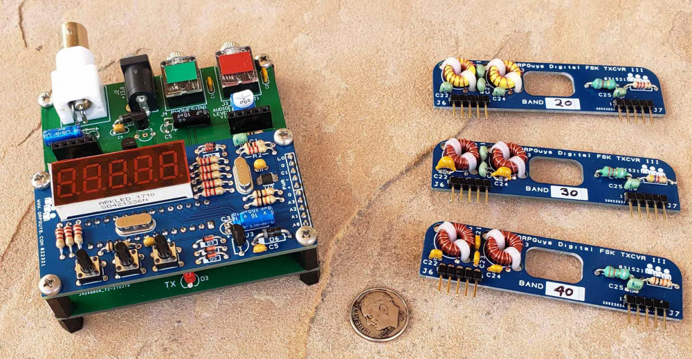
The new QRPGuys AFP-FSK Digital Transceiver III kit for 160m-6m is a low cost, multi-band, multi-digital mode, 5 watt transceiver kit, with VFO and plug-in module kits supplied for 40/30/20m.
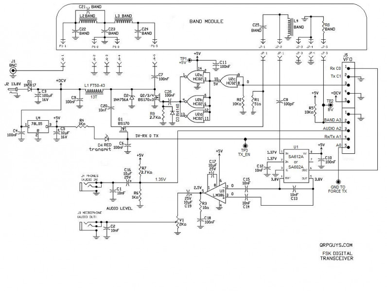
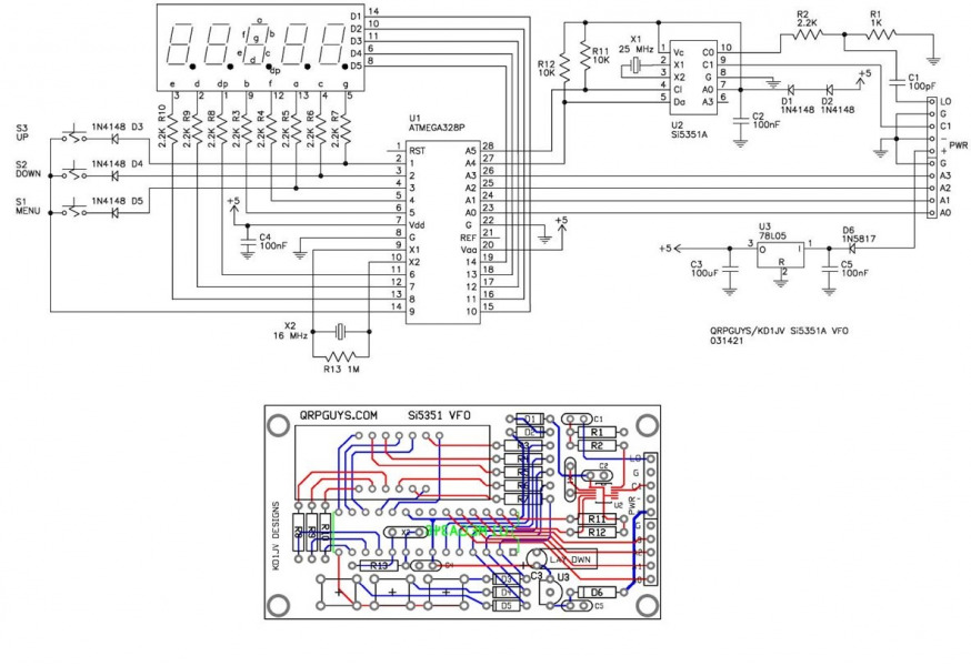
The v. III version debuts a novel firmware scheme for our Si5351A/MS5351M VFO which allows a move away from DSB transmission to SSB, by a new process we are calling AFP-FSK (Audio Frequency Processed-FSK). The SSB transmittted signal is generated by a unique process of measuring the input audio frequencies, then through software, producing the RF frequencies (pure FSK, not AFSK) directly by the VFO, eliminating the need for any mixing which creates unwanted sidebands. This innovative firmware and related hardware design changes by Kazuhisa “Kazu” Terasaki (AG6NS) and Steve Weber (KD1JV), allow ~5W signal on bands from 160m thru 15m, ~4W for 12-10m, ~1W for 6m, using FT8, FT4, JS8CALL, WSPR, and RTTY modes. Though effective sensitivity is somewhat dependent on sound board quality and can pull signals out of noise, 0.1uV on the lower frequency bands and slightly less sensitive on the higher frequency bands is typical. The board is the same size as earlier versions, (3.0″ x 3.12″), and all the components are included for the transceiver, VFO, and band module kits for 40/30/20m. Bare module boards are available for additional bands. Each band module has automatic sensing to set the VFO to the appropriate band at start up.
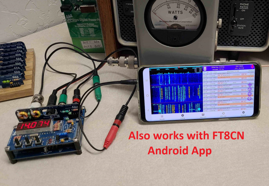
The transceiver runs the popular free digital programs. Some programs require an accurate time synchronization program, such as Dimension 4, or many of the other free ones available. Users will need two generic 3.5mm stereo jumpers to your computer or tablet microphone/speaker jacks on the sound card.
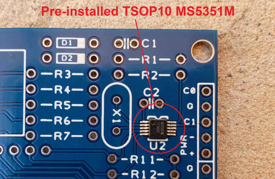
The main board has all through hole components except three SMD ICs. The VFO board has the MSOP10 Si5351A/MS5351M PLL IC pre-installed, all the remaining components are through hole including the band modules. All the hardware and standoffs are included for compact desktop operation. The connections needed to the transceiver are male BNC for the antenna, 3.5mm stereo jumpers to the computer audio jacks, and a 5.5mm x 2.1mm pin coaxial power plug for the supply of 12-14 VDC. Power consumption at 13.8V is about RX-65mA / TX-600mA. The total weight w/three band modules is <3oz. (82gm). The normal tools required are a soldering iron with a small tip, rosin core solder, small side cutters, and small phillips screwdriver. The transceiver and VFO can be built in an evening or two. On a difficulty scale of 1 to 5, 5 being the most difficult, this is rated at 3 to 4 depending on your experience.
Click here for the transceiver and VFO assembly manual
Click here for description of the AFP-FSK method
Click here for the Arduino sketch for customizing
Click here for the some of the popular digital frequencies
Click here for suggested pcb fabricated chassis drawing
Other reference URLS:
Excellent FT8 Users Guide by ZL2IFB
https://physics.princeton.edu/pulsar/K1JT/wsjtx.html – Latest WSJT-X program
Dimension4 download – Coordinates computer time
https://time.is/ – Checks time accuracy of the computer time