This product is discontinued.
With the openings recently on 10 meters, it reminds us of the days for DX potential on that band with low power and smaller antennas. The absence of many budget kits for this end of the HF spectrum led us to approach Steve Weber (KD1JV) for a low cost kit design.
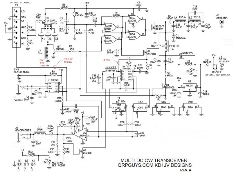
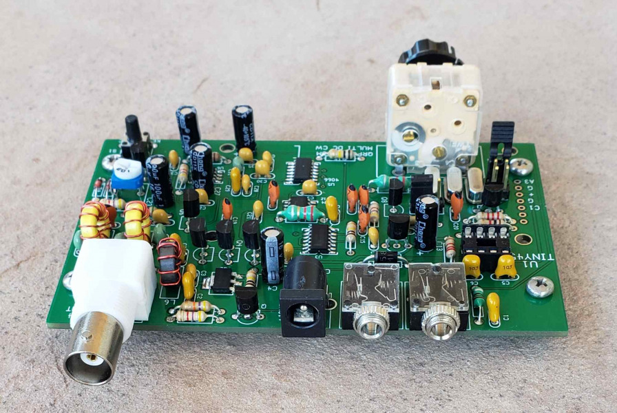
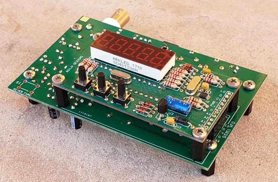
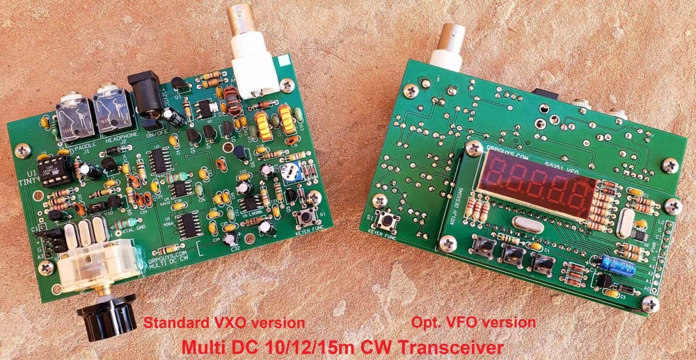
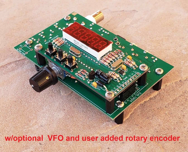
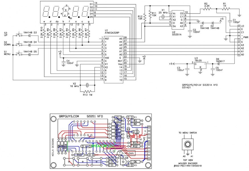
Steve then designed the Multi-DC CW Transceiver offering a three band transceiver that is optimized for 15m through 10m. Supplied are three switchable fundamental crystals of 21.060, 24.906, and 28.060 MHz for the QRP calling frequencies on 15, 12, and 10m, with RIT for ~8 kHz bandspread. The power output is 4-5W on 10/12m and ~3W on 15m at 13.8V. For less power, 1.5-2W, decrease the supply voltage to 8.0V. Receiver sensitivity, MDS ~0.1 uV on 15m, ~0.2uV on 12m, and ~0.5uV on 10m. Included, is an onboard header for connecting our optional Si5351A/MS5351M PLL VFO for full band coverage and RIT on all three of the bands, enabling you to listen to SSB stations in the phone segment of the bands, and general coverage SWBC stations outside the ham bands.
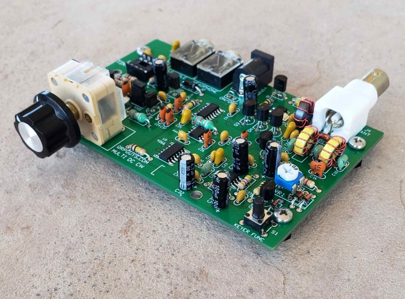
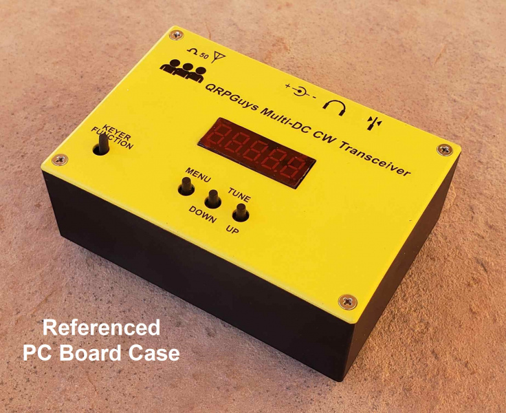
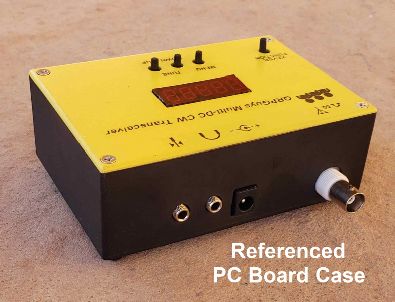
Built into the transceiver is Steve’s popular ATtiny45 SKC keyer with adjustable speed from 5-30 WPM, two programmable memories of 60 characters, straight key mode, and beacon mode if starting your own 10m propagation beacon is desired. All the controls are on the top, and I/O connections are out the back of the pcb for easy mounting. The input power of 8.0 to 13.8VDC is via a standard 5.5mm x 2.1mm coaxial jack. Audio output and paddle/key connections are standard 3.5mm jacks. The antenna connection via a board mounted female BNC connector is standard. Rx current consumption is a low 15 ma without the VFO, and 45 ma with it. Tx current consumption is 850 ma max. at 13.8V. Weight is 2.4oz. (68gm.)
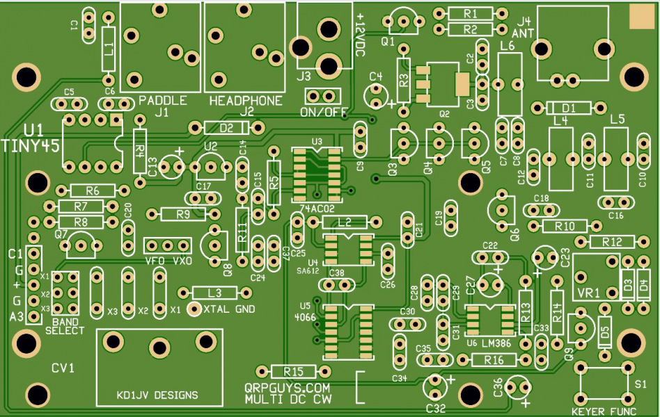
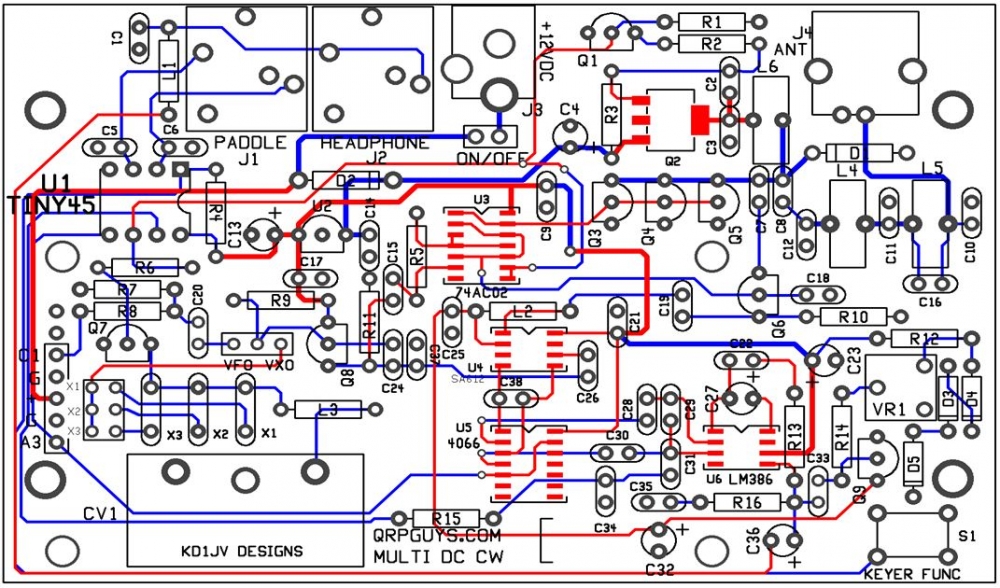
He designed the board measuring 4.20” x 2.65” to fit into a referenced ABS plastic enclosure available on eBay for portable operation. We also supply details for a pcb fabricated case should you decide to go that route. However, this kit contains all the hardware that will allow full desktop operation for crystal controlled or VFO option without an enclosure.
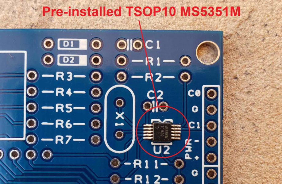
The through hole components are comfortably spaced, including the socketed ATtiny45 keyer chip, four of the IC’s are SMD. The optional VFO has the MSOP10 Si5351A/MS5351M PLL IC pre-installed, the remaining components on the VFO are through hole. On a scale of 1 to 5, 5 being the most difficult, this is rated as a 3-4. The normal tools required are a soldering iron with a small tip, rosin core solder, small side cutters, a small Phillips screwdriver, and some Solder Wick® if needed. Allow an evening or two to build, depending on your experience.
Click here for the transceiver and VFO assembly manual.
Click here for Steve’s suggested blank ABS plastic case on eBay.
Click here for a suggested user fabricated pcb chassis.
Click here for the Arduino sketch for customizing